
Chamber furnace, metal insulation HTK
The metallic HTK range of Carbolite Gero high temperature furnaces consists of metal heaters made of Molybdenum or Tungsten.
The HTK series, made of metal, is available in four distinct sizes. The smaller HTKs with capacities of 8 and 25 liters are usually used in laboratories for research and development. The larger 80 and 120-litre furnaces are mostly utilized as pilot manufacturing systems or for large-scale production. The front door design of these furnaces allows for easy loading and unloading.APPLICATION EXAMPLES
carbon free atmosphere, metal injection moulding (MIM), metallization, sintering, thermal debinding, pyrolysis, synthesis, annealing, tempering
OVERVIEW
| Furnace Type | Usable Volume | Max temp | Number of heated zones | Debinding Option |
| HTK 8 MO/W | 8 | 1600 °C / 2200 °C | 1 | Torch/ condensate trap |
| HTK 25 MO/W | 25 | 1600 °C / 2200 °C | 1 | Torch/ condensate trap |
| HTK 80 MO | 80 | 1600 °C | 4 | Torch/ condensate trap |
| HTK 120 MO | 120 | 1450 °C | 4 | Torch/ condensate trap |
STANDARD FEATURES AND OPTIONS
- Metallic furnaces provide a precisely defined atmosphere with the highest possible purity
- Metallic furnaces offer the best possible vacuum
- Hydrogen partial pressure operation is optional available
- Data recording for quality management: CC-TP1200 smart, CC-TP1900 or CC-IPC1900
- Option for debinding processes
- Option for clean high vacuum processes
Required infrastructure
- Gases: hydrogen, argon, nitrogen
- Electric power supply
- Fail safe cooling water
- Exhaust
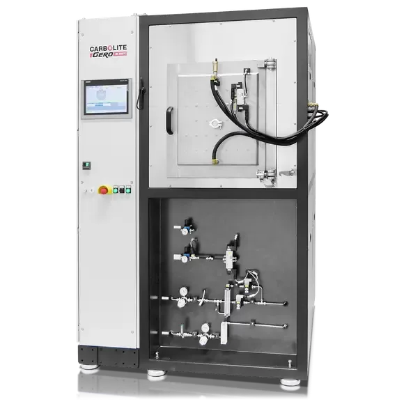
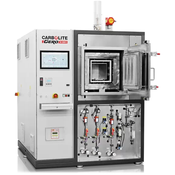
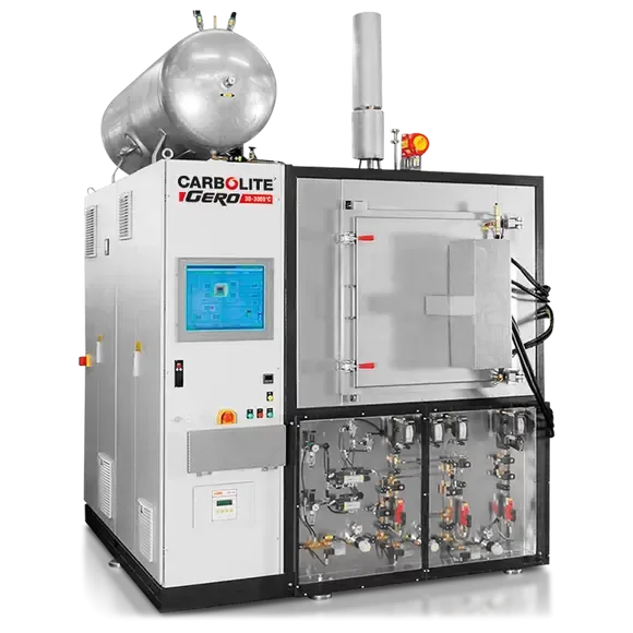
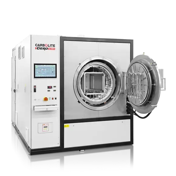
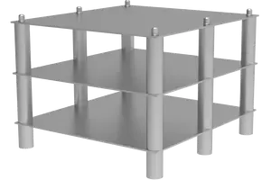
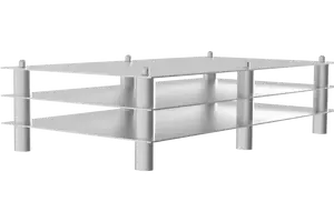
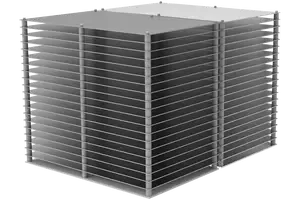
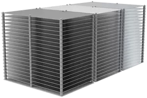
| HTK 8 | HTK 25 | HTK 80 | HTK 120 | |
| Usable space in the retort H x W x D [mm] | 160 x 180 x 180 | 240 x 240 x 400 | 380 x 410 x 500 | 380 x 400 x 770 |
| Number of plates* | 3 | 3 | 40 | 60 |
| Plate dimensions [cm²] * | 225 | 860 | 930 | 930 |
| Picture of sample rack |
|
|
|
|
EXPLANATION OF THE DEBINDING AND SINTERING PROCESS STEPS OF THE HTK-MIM-3 FURNACE
The HTK-MIM-3 furnace program enables debinding and sintering of MIM components in two stages. The program's progress is displayed in a diagram, and important parameters such as pressure, gas flow, and gas type are recorded. The debinding stage utilizes partial pressure and high nitrogen gas flow, while the sintering stage focuses on temperature uniformity, resulting in a consistent density of the MIM parts.
INSIDE THE FURNACE
HTK 8 – 80 furnaces consist of: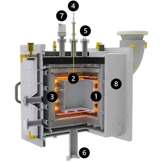
- Heaters
- Retort
- Radiation Shields
- Thermocouple
- Gas Inlet
- Gas Outlet
- Vacuum Gauge
- Water-cooled vacuum vessel
Exemplary cross section of a HTK 8 molybdenum
HTK 120 furnaces consist of: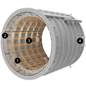
- Heaters
- Radiation Shields
- Gas inlet
- Gas Outlet
Heating cassette of the HTK 120, CAD drawing. Designed for highest lifetime and easy maintenance.
BINDER HANDLING OPTIONS HTK8 - 80
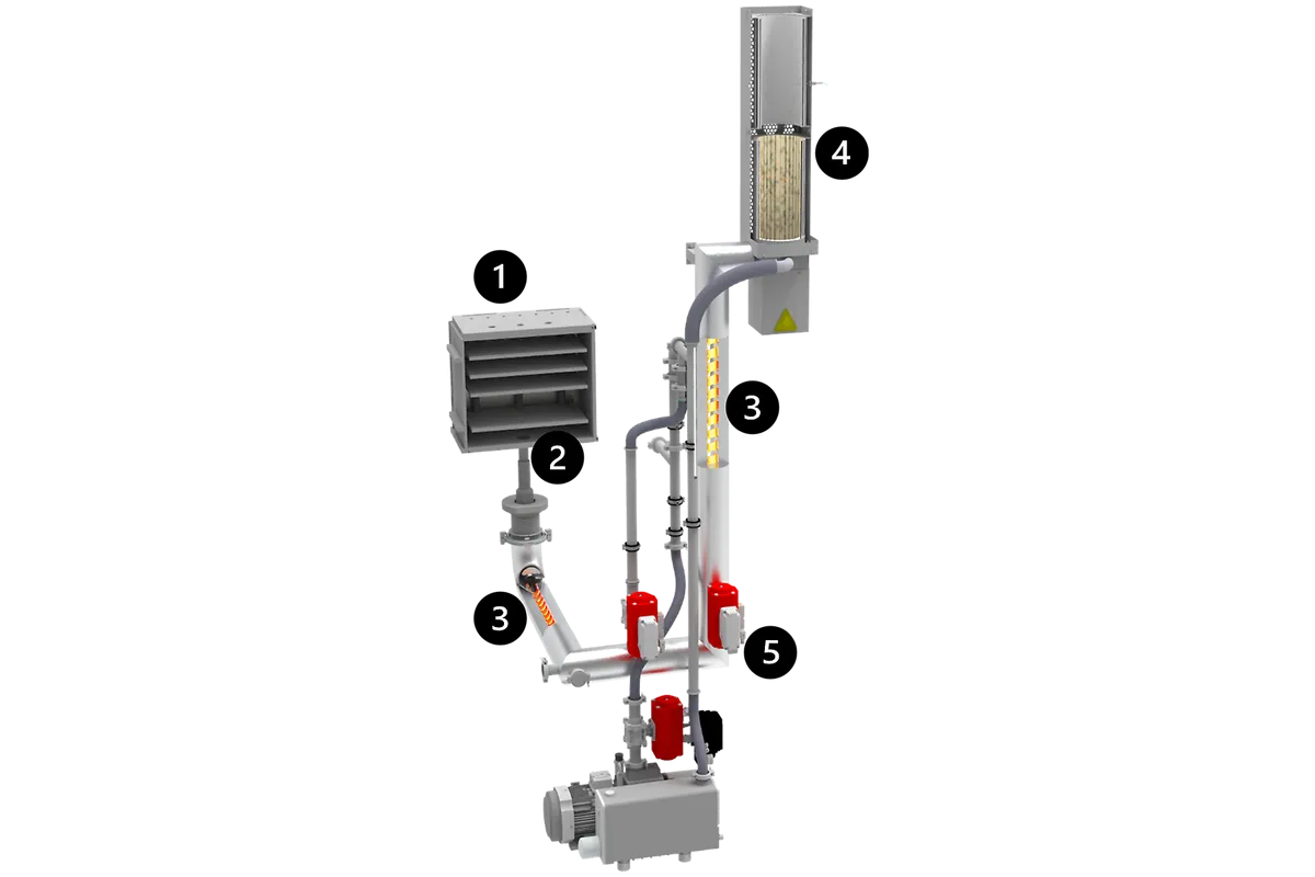
AFTERBURNER ASSEMBLY:
- Retort
- Gas outlet
- Trace heating
- Torch
- Position controlled ball valve
The torch of the afterburner ensures controlled conversion of remaining flammable or toxic volatiles into non-flammable gases.
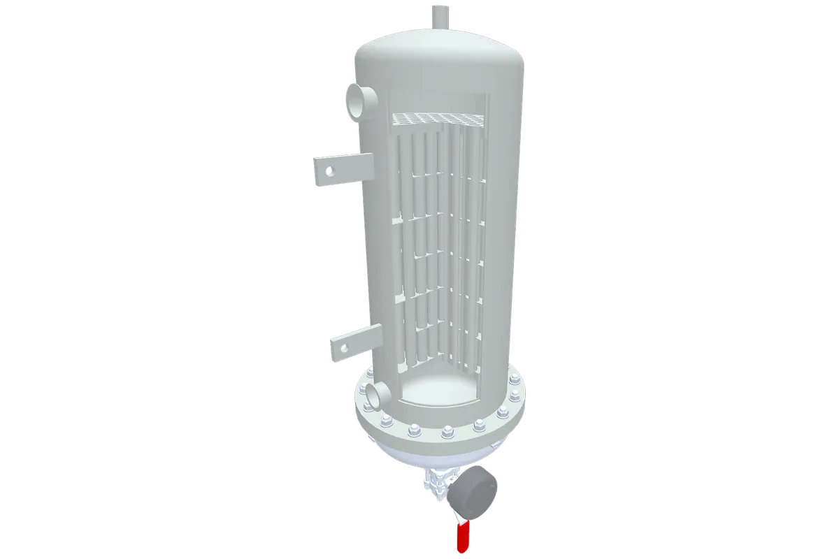
The condensate trap may be installed for binder handling. During the process the trap is cooled to condense the binder. After the process the trap can be heated to release the binder safely which has been liquified.
Afterburner
Condensate trap
SOME HTK120 OPTIONS
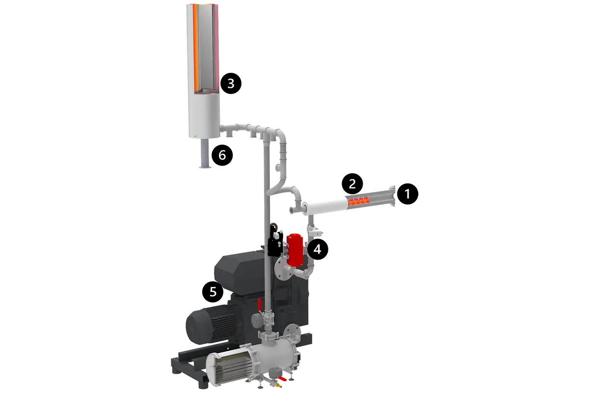
AFTERBURNER ASSEMBLY:
- Gas outlet
- Trace heating
- Torch
- Position controlled ball valve
- Fresh oil pump
- Oil condenser
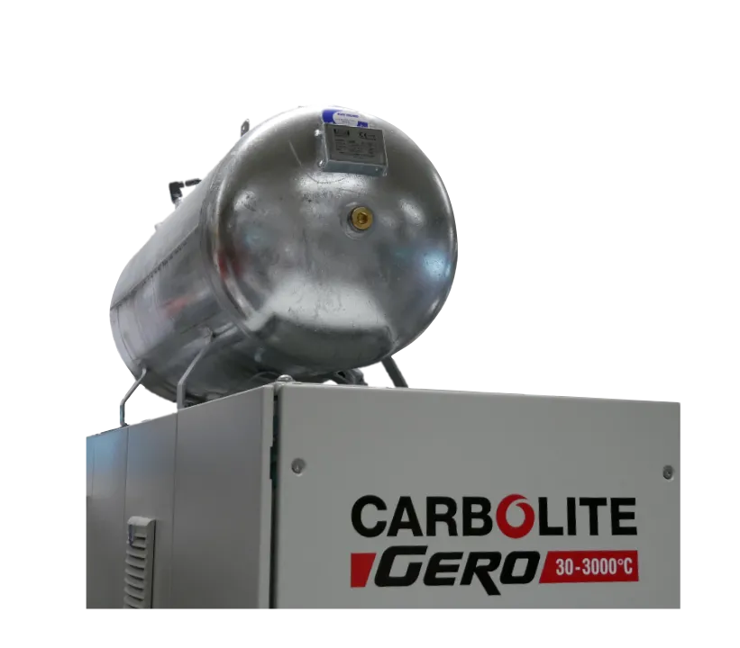
The stand alone safety purge tank ensures full safety for hydrogen applications. The furnace can only be started, if the tank is completely filled. Therefore the furnace is flood with nitrogen gas in case of major errors, such as power failure etc. The size is adjusted according to the furnace volume.
Heated gas outlet and vacuum line of the HTK 120
Stand alone safety purge tank
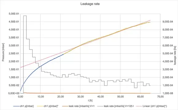
LEAKAGE RATE RESULTS
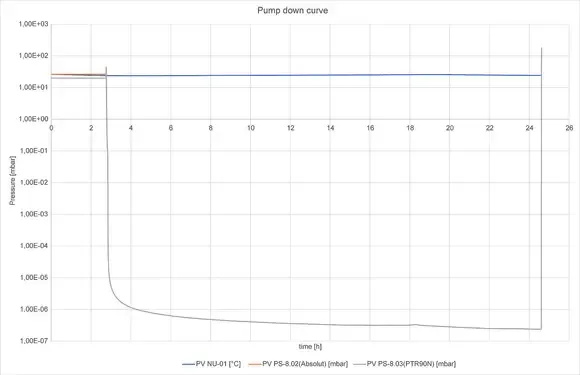
With the high vacuum upgrade the leakage rate results in values below 10-3 mbar*l/s. The leakage rate is determined by evacuating the furnace, closing all valves and meassuring the pressure increase over time. The desorption of water molecules from the metal surface takes approximately 20 h, and leads to a faster increase in pressure, represented by the blue line.
HIGH VACUUM APPLICATIONS
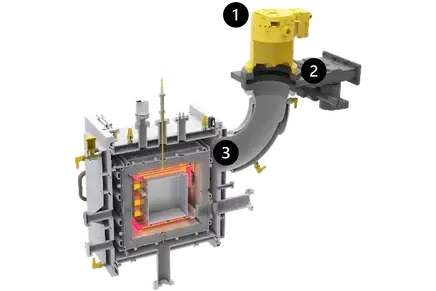
Cross section of HTK 8 with high vacuum upgrade. The turbo pump is at least connected via an DN100 flange.
- Turbo pump
- Vacuum valve
- DN 100 flange
High vacuum upgrade
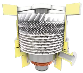
Schematic of a turbomolecular pump for high vacuum applications.
CONTROLLER OPTIONS
The furnace is operated via a 12" or 19" touch panel controller. It provides an overview of the furnace and its behaviors and allows the user to preform any possible adjustments to the furnace.
- User friendly 12” touch panel, provides a detailed overview of the furnace status.
- Configuration of an automatic programm
- The smart software is mainly used for simple processes
- The full automatic function ensures full flexibility
- The pre-program ensures that the furnace is evacuated prior to heat treatment to ensure safety in case of any occuring errors
- The system is based on an industrial standard Siemens PLC ensuring full safety.
| Size of Panel | 12 |
| Number of programs | 12 |
| Export data | csv |
| Remote access | Yes |
| Keyboard | No |
| Remote maintenance | No |
| Online changes | No |
| MFC | Yes |
| Rotameter | No |
| Heated gas outlet | Yes |
| Turbopump | Yes |
| Hydrogen | No |
| Partial pressure | No |
| Sliding TC | Yes |
- Full visualization of the furnace with 19’’ touch panel, mainly for fully configured units or for the use of hydrogen (>5%)
- Configuration of an automatic program
- The automatic software is used for more complicated and hydrogen processes
- The CC-IPC1900 version additionally includes an industrial PC with standard windows software
- The system is based on an industrial standard Siemens F-PLC ensuring full safety even for hydrogen applications
- The pre-program ensures a fully automated leakage test which takes place in overpressure and vacuum
| Size of Panel | 19 |
| Number of programs | 20 |
| Export data | csv |
| Remote access | With Siemens software |
| Keyboard | Optional |
| Remote maintenance | Optional |
| Online changes | No |
| MFC | No |
| Rotameter | No |
| Heated gas outlet | Yes |
| Turbopump | Yes |
| Hydrogen | Yes |
| Partial pressure | Yes |
| Sliding TC | Yes |

